
MPC 2000XL
Main Article: Akai

| Release Date | 1999 |
| Inputs (Balanced) | 2 1/4″ TRS |
| Outputs (Unbalanced) | 2 1/4″ TS, 8 1/4″ TS (Optional), 1 1/4″ Headphones |
| MIDI | 2 MIDI In, 2 MIDI Out |
| DAC | 16-bit |
| ADC | 16-bit |
| Sample Rate | 44.1 kHz |
| Polyphony | 32 Voices |
Operating System
To check your operating system hold SHIFT and press 8 (OTHER), then press F3.
Audio Format
The 2000XL saves audio in the Akai (.SND) format by default. Programs using SND files will load slightly faster than those containing WAV files on older model MPC’s (MPC 60, 3000, 2000, 2000XL). SND files are not compatible with MPC’s running JJOS.
| System | Default File Format |
| MPC 60 | .SND format only (12-bit) |
| MPC 3000 | .SND format only (16-bit) |
| MPC 2000 | .SND with .WAV Support (Programs must contain .SND) |
| MPC 2000XL | .SND with full .WAV support |
| MPC 4000 and Newer | .WAV (with .SND support) |
File Conversion
WAV files must be in 16-bit PCM format before converting to SND.
8-Output Expansion Board
The following expansion boards are compatible with the 2000XL
| System | Board | Requirements |
| MPC 2000 / MPC 2000XL | IB-M208P | Mounting Plate, Mounting Screws |
| S2000 | IB-208P | Modified Mounting Plate, 34-Pin IDE Extension Cable |
| S3000XL | IB-208P | Modified Mounting Plate, 34-Pin IDE Cable |
Installation Guide
Remove the 14 screws under the MPC and remove the bottom plate
Remove the 8 output cover by removing the 2 screws that are holding it place
Insert the 8 output board and secure it in place with 5 screws on the back of the unit. If you are using a donor S2000 or S3000XL you may be able to use screws from it, along with the the 2 screws that were holding the 8 output cover in place.
Secure the mounting plate with 2 screws into the 2 brass posts in your case. If you are using a modified mounting plate from an S2000 or S3000XL you may also choose to ground the board with a wire going from the 2 corner screws going into the 2 brass posts.
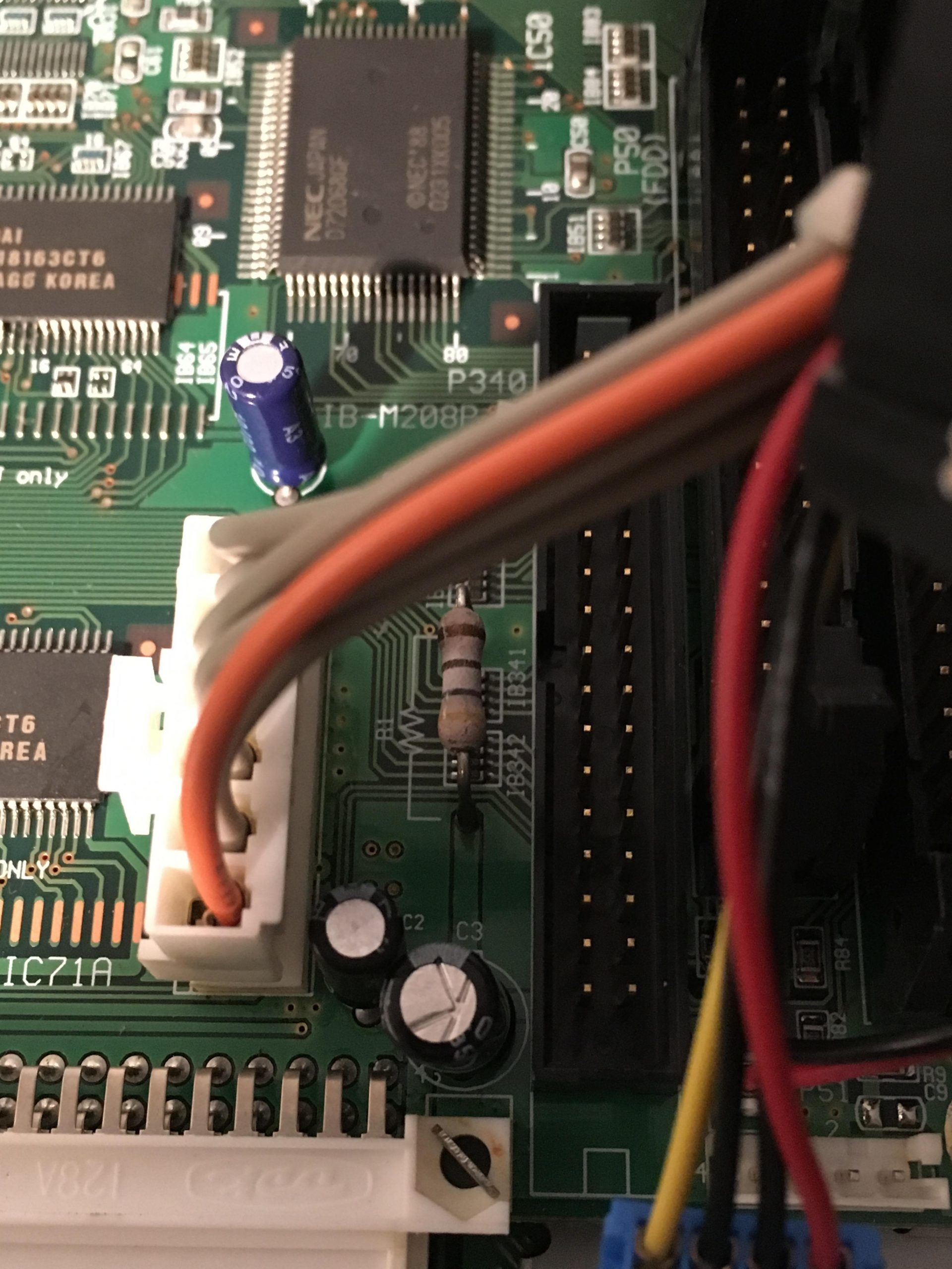
Plug the 34 pin cable into the board next to the floppy drive. The red line on the cable should be inserted on the side with an arrow pointing to it. Some S2000 boards have a cable soldered on with the red line on the opposite side of the cable. You will need a 34 pin extension cable to install this board. If the cable is too short, and removable, you can use a normal 34 pin cable from a floppy drive to install the board.
Note: If you have abnormally low sound coming from the 8 outputs and you are using 1/4″ TRS cables you may need to switch to TS cables as these outputs are unbalanced.
Incorrect Installation Fix
Symptoms: Pads not working, no audio output
Cause: Installing 34-pin cable backwards
Solution: Replace resistor labeled “R1” next to 34-pin cable input

Carefully unplug everything plugged in to the motherboard
Unscrew the 2 screws holding the Stereo Out in place, unscrew the 4 screws holding the MIDI module in place, unscrew the 2 screws holding the SCSI output in place, unscrew the SMPTE module with a ratchet and socket
Remove the 4 four screws holding the motherboard in place
Flip the motherboard over and desolder and remove the R1 resistor
Install the new resistor at a similar height and snip the excess wire after soldering